In December there was a lot of press about Hour of Code; they managed to get Barack Obama to write some code (and David Cameron, but does anyone really care?). The site was also really lucky to strike a deal with Disney to be able to use Elsa and Anna from Frozen. As any primary school teacher knows, Frozen is a sure fire way to get the interest of nearly any KS2 girl!
So, what’s it all about and is it any use? I set my year 5 and 6 kids to have a go and work through the exercises, needless to say the girls enjoyed it more than the boys and were quite chuffed with their certificates (even the hardened Year 6 girls who like to pretend they’re too cool for Frozen), whereas my boys scrolled down the site and found the Angry Birds game and gave that a go.
I’m really impressed with the Frozen resource not least because it works on iPads as well as on a laptop.

The first thing you see when you go to the site is a video explaining why computer science is important – the first minute or so includes Bill Gates, Mark Zuckerburg and the guys who created Dropbox and Instagram as well as programmers from Google and Microsoft. We are also introduced to two models, one of whom is a complete beginner at coding and one who studied computer science as well as theatre at college – it is through the latter of these, Lyndsey that we learn about the the Frozen code – we will be guiding the characters through various ice skating tasks using Blockly (similar to Scratch), which is a block based language of code. The remainder of the video features Lyndsey explaining how Blockly words, although anyone familiar with Scratch should be able to pick it up quite quickly.
So how does it all look:
Each puzzle begins with a splash page explaining what to do

Then you are taken to the main coding window – like other block based languages, it’s just a drag and drop activity.

You will notice that the goal for this task is repeated in the bottom left of the window.

So here you can see my first line of code – its useful to note that the instruction video doesn’t mention the “when run” block that your code needs to be attached to – presumably this was added after the video was made.
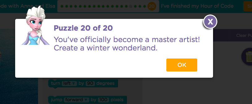
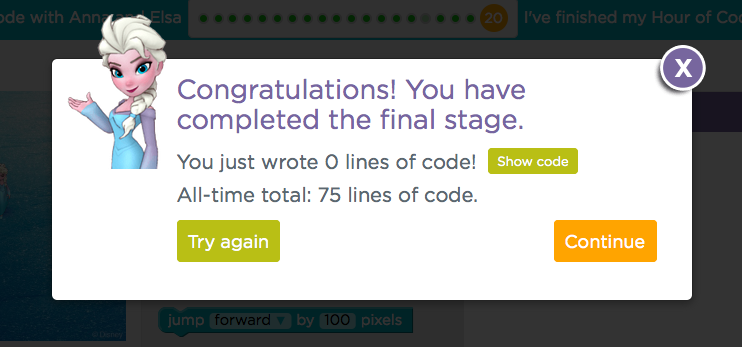
You also get a nice little congratulations window at the end of each puzzle:

So puzzle two just adds a simple right hand turn – I asked a teacher to have a go at this task and she managed to completely forget to add a forward block after the turn, which is also a common mistake children make so be prepared for this!


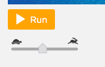
There are a couple of other nice features as you work through – firstly, when you run your code your animated Elsa walks through what you’ve asked her to do, flinging snowflakes as she goes and this can be quite irritating after a while, so you can speed up the code using the hare and tortoise icon below the ‘run’ button.
 Secondly, after you’ve completed the level you can click on the ‘Show code’ button and it will show you what your code looks like in JavaScript, which is a feature that really appeals to the older children I teach.
After lesson 3, we’re introduced to Paola, who works for microsoft and explains loops to us ready for Anna’s task, which requires loops and a bit more thinking to figure out.

Anna’s first task simply involves putting our first loop in, but the second involves reading the instructions carefully! The code is pre-written and all the user needs to do is change a couple of variables.

Now we’re starting to get a bit trickier with our activities, but we’re still presented with the code first and asked to make alterations to the variables:

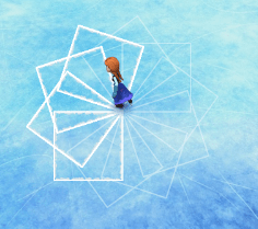
Puzzle 8, unfortunately, expects our children to know how many  degrees are in a full turn and then use that to calculate that Elsa needs to turn 36 degrees each time to make a star pattern that has ten points, but I guess with trial and error the children could get it since there are only a few options on the drop down menu.
Then we’re asked to do it 90 times, but with a subtle hint as to what angle we need (the options are 4, 45, 60, 90, 180 and 360, so it is kind of obvious).


We’re also rather casually introduced to a change colour variable here, which is lovely, but a bit unexpected!
 I’m not going to lie, the maths teacher in me got a little overexcited when it saw the next activity was all about drawing parallelograms, until I got really frustrated by drawing rhombuses that had been labelled as paralleograms – I mean seriously, the amount of time I spend explaining that if a parallelogram has 4 sides of the same length then it’s a rhombus – I suppose it could have been worse, they could’ve called it a diamond. But in all seriousness, it’s great that the children are being encourage to think about shapes and angles in this much detail!
Interestingly, for all of the activities after they randomly dropped it in, the set colour block has been in your toolkit and there is a block space for you to drop it in should you desire, but it still hasn’t been explained – I’m assuming this is some kind of bonus for the able kids who will figure out what it does and feel pleased with themselves for self-extending.
After coding Anna to skate in a circle, we are given another video where Chris, an NBA star and coder uses basketball as a metaphor for functions – I’m not going to lie, it’s a lovely idea, but the concepts of functions are not an easy one to understand – I’m still a bit bewildered even after a year or more of trying! In the video, Jess (CEO of a company I’ve never heard of), shows u s that we can call our earlier code to draw a square ‘square’ and define that as a function so that whenever we call ‘square’ that piece of code is run – this concept is very clearly shown by the diagram embedded in the video, but I still feel like it may be a bit too difficult for a child to understand.
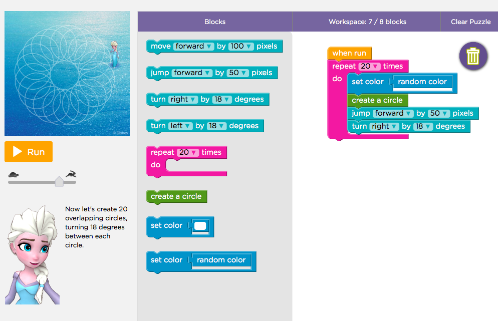
 Fortunately, we don’t actually need to understand the concept of a function, we just need to understand that we can now simply drop the ‘create a circle’ function into the code and it does the circle drawing code for us!
 You’ll notice that the ‘set color’ option is still being snuck into every activity.
The next few activities really needs us to start thinking:

The clues are there for what angles you need, but it’s not as explicit as it was in the beginning. Still, I’m making some pretty pictures, and I’ve become slightly obsessed with putting the random colour block in…
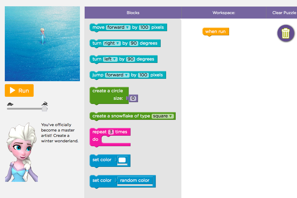
 So, finally, I’ve managed to get onto the final task and earn my certificate! The final activity is a freeform drawing page and I just left mine blank and still got a well done. Hooray for me! I even managed to publish my certificate to twitter.


So, some conclusions – the Frozen activity at Code.org is a fantastic way to get kids interested in coding, especially girls. It gets tricky, but it’s not impossible with a little patience, especially as all of the tools are there and the drop down menus don’t give you too many options – even with trial and error you’d get it right in the end. I also liked that it gets adults more enthusiastic about code too – I showed this too my Year 3 teacher, who previously just didn’t get the point of coding and we ended up with several members of staff around the table getting invovled and asking questions – including “how is this coding?” which of course meant I had the opportunity to jump in and explain that block based coding teaches algorithmic thinking and just basically doing things in order. Year 3 are going to try this out next term because she enjoyed herself so much, although I am concerned that some of the angle work later on might be a bit too tough for them…
Overall this is a great activity and I can’t wait to try out some of the other resources on the site.
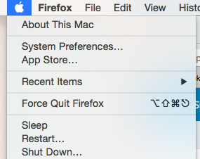 First, click on ‘about this mac’, then ‘system report’:
 Finally, select ‘card reader’ to get information about the disk – you will see that mine says “BSD name: disk3” so, very simply, my SD card is disk3.
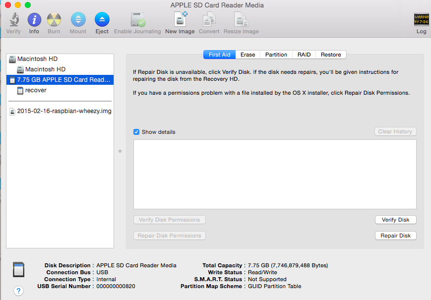
 The next step is to open disk utility which can be found in utilites (accessed by typing in shift +⌘ + u):
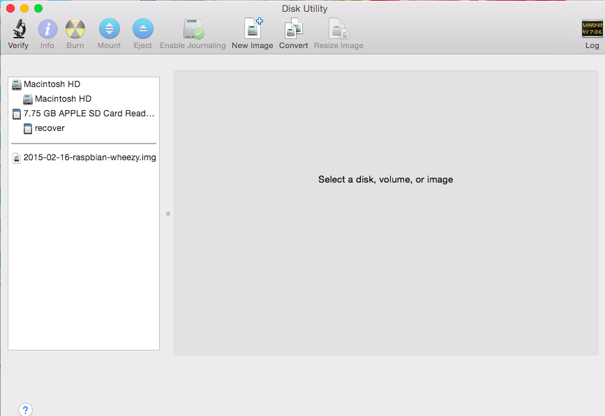


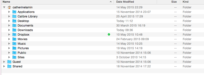 So terminal has automatically opened the ‘myname’ home directory.
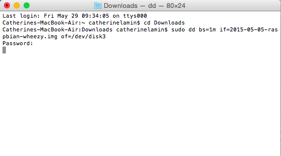
 This is where I hit on a real problem – the Raspberry Pi site suggests typing this into terminal:
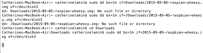 So, my final code looked like this: