After the success of my first post, thanks to Raspberry Pi tweeting about it, I thought I should move on to the other three worksheets that come with this pack (there are another two in the process of being made). I’m really pleased with the feedback I’ve received and I’m really looking forward to seeing the new improved sheets that Tim Richardson is hoping to create using some of the things I said in my blog – another reason why these are such a great resources, the developers are willing to listen to feedback and use it to improve their work! Thanks guys.
So, the next three sheets are entitled: User Input, Button and Buzzer. I’m curious to see what exciting things I’m going to create this time round!!
The first thing I need to do is rebuild my LED circuit from sheets two and three (my bad for dismantling it after the last blog – stupid need to tidy things neatly away) – now that I feel a bit more comfortable with the bread board etc this should be a bit easier!
Circuit built from memory, I was about to plug it in then remembered my own warning from the end of the previous blog and carefully checked that I hadn’t made a silly mistake (once again I’m so grateful for my PiBow Coupe case with the pin numbers all marked up for me). I turned on the pi and thought it was well worth checking my circuit was set up correctly by running the blink programme I’d made in sheet 3 – it took me three attempts to remember how to access the directory where the programme was stored (cd EduKit was the code I needed), but eventually I got my LEDs flashing and was ready to move on to my new task. It was only after I opened up the worksheet to get to work that I realised that the first line of code on the worksheet helpfully guides you to the right directory – well done me!!
So, once again we’re jumping up in the difficulty scale with significantly harder lines of code here. On the one hand the user could quite conceivably copy the code and get the results without any understanding, but the joy of these worksheets is that they do explain what many of the lines of code mean so that people like myself with little or no knowledge can begin to understand what we’re actually doing.
Most of the code that we’ve seen before is explained with hashtags as in the previous sheet, but some of the more complex code is not fully explained and instead is simply summarised – I think I would have preferred having the option to understand more layers of the code, for example that if you put
print "words are here"
whatever is enclosed in the speech marks is printed to the screen on running the programme, however, I appreciate that the CamJam guys are trying not to overcomplicate things – perhaps a sort of glossary of new code terms could feature at the end of the page for the geeks like me who want to go deeper? The same is true of lines that involve == and of course > which I understand as a maths teacher, but sadly there are plenty of teachers out there who may not understand is meant by the less than, greater than signs!
Overall though, this is another great worksheet and I had fun trying out the different combinations. I had two debugging problems this time around, the first being that for the green LED I’d managed to type ++ instead of == which meant it kept only selecting the green LED and the second was a sneaky space bar which slipped into one line of code before a bracket meaning that the LED just flashed once and ignored the count command. I also nearly forgot the final line of the code to clean up the GPIO pins, but I remembered in the earlier sheet that this was stressed as important so I quickly tweaked my code to include that line.
This time the sheet finished with “do not disassemble this circuit” so I was ready for worksheet 4 and my button.
As with worksheet 2, we are once again introduced to the new components (the button and the ‘other’ resistor in the pack). I’m afraid I couldn’t quite get my head around the concept of a ‘pull-up resistor” from reading about it on the sheet, but I’m hoping this will make more sense once I’ve built the circuit, or else it won’t be something that I need to understand in detail.
As soon as I began to construct the circuit it became more clear – in the previous circuit, the resistor sat between the ground and the LED making part of the completed circuit, this time my circuit goes ‘live’, resistor, GPIO input, button, ground with the resistor sitting neatly between the live input and the button itself. I think I know how it works now.
At this point I’ve realised I have yet to discuss the different types of pins on the Raspberry Pi, so a quick run through – there are 3 main types of pins: live, ground and GPIO. if you connect a circuit from live to ground with an LED in the middle, you will have a lit LED – the live does not work based on any input from the Pi, it is ‘always on’. Live pins can be either 3.3v or 5v. Every circuit needs to be connect to a ground pin, which is what makes bread boards so useful, you can utilise one row to take all of the ground connections, however, there are several grounds on the Pi to make things easier. Finally you have the controllable GPIO (general purpose input/output) pins which can be numbered in one of several ways, but the most common is BCM numbering and this is what is marked on my case. The key thing to remember is that every circuit must end at a ground.
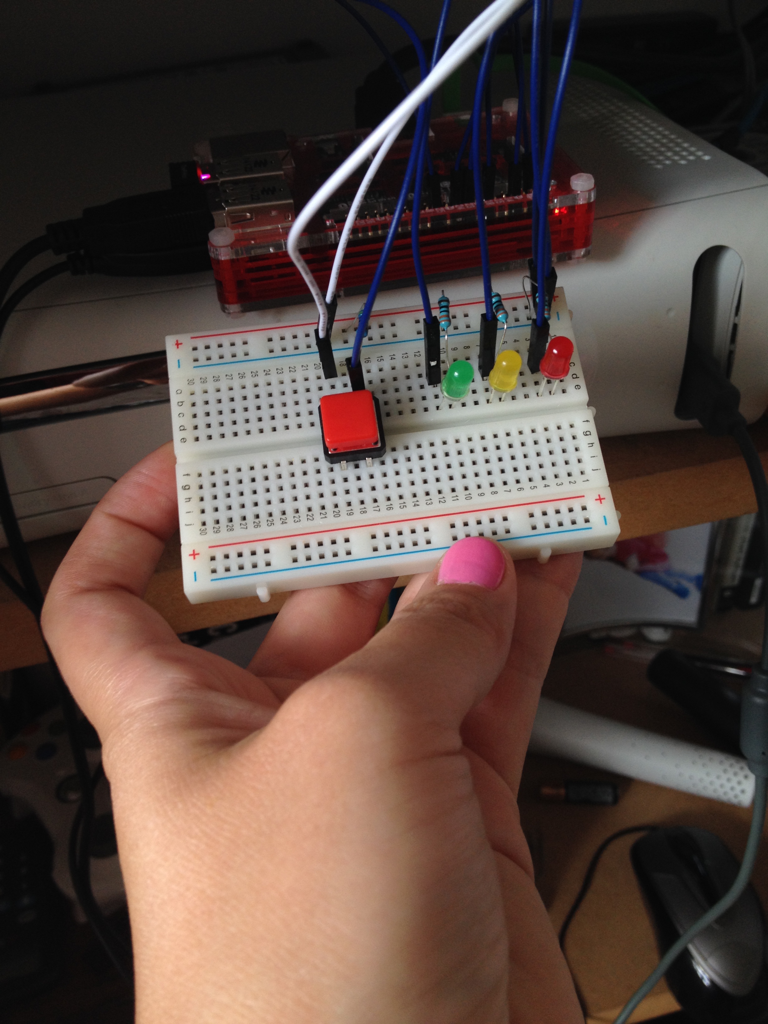
Anyway, back to my circuit, which now has a nice, shiny button installed
It’s almost as though the creators of the sheet read my mind as this time all of the new commands ARE explained in a box at the end – fantastic!!
This was a fairly easy sheet to work through and this time I only made two minor mistakes (I accidentally put a capital P for print and I forgot my semicolon after the else command). What I’m really appreciating is that in the terminal box the common commands helpfully colour in if you’ve spelt them correctly so if I type print it becomes a lovely turquoise colour and if I remember to put speech marks either side of my printed messages then they go a lovely green colour, it’s great for debugging and makes the lines of endless code look a little bit more interesting.
On this page I also really like the simple end paragraph along the lines of “this will keep going until you press ctrl + c” because I think I probably would have panicked without that instruction. So sheet 5 is getting a massive thumbs up and I’m pleased that my button does something (even if that is just to print “Button Pressed and 0” to the screen).
No instruction to keep the circuit, but I’m not taking any risks as we move onto the final sheet, the buzzer.

I almost feel a bit sad that I have used everything from my tin to create the final piece of my circuit – this time the worksheet begins by explaining what a function is and how you go about defining and calling one, which is fantastic. This is something I’ve sort of got my head around from Codecademy, but seeing it explained another way has helped to consolidate my understanding! My final task then, is to programme the buzzer to beep out “SOS” in morse code and repeat it a user defined number of turns.
So, once again another successful and easy sheet to follow – I’m really beginning to enjoy myself and sad that I’ve run out of sheets. My mistakes this time were really silly – in my haste to finish I missed out an entire function so when I tried to run my programme it told me that ‘wordSpace’ was not defined. There is a great little extension task on the end of this sheet so that after you’ve made the buzzer beep out SOS you can think about the code for making it do more letters. My gut reaction is that I now want to be able to use the button to make the buzzer go off and I’m already trying to think about how I would programme that so these sheets have really got me thinking, but more importantly, they’ve really helped me to understand python through practical application and I’m feeling a real sense of achievement.
Once again, a great resources from CamJam and well worth the investment in the EduKit tin – I’m really looking forward to letting my Year 5 and 6 Code Club have a go at working through them all and seeing what their reactions are.

One thought on “Raspberry Pi – CamJam EduKit (part 2)”