This weekend I decided it was time to try out the rather exciting CamJam EduKit 3 – Robotics
I admit that I’ve been avoiding having a go because I was terrified of everything going wrong, so this weekend I called my friend and we embarked on our first robot building exercise.
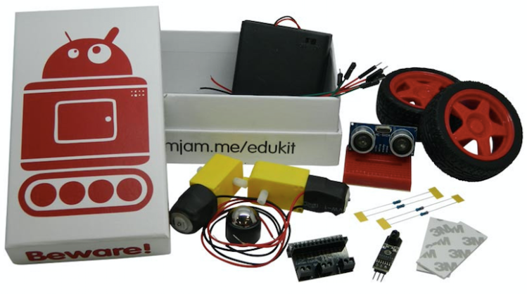
So…in the kit are all the parts you need to build a robot – once again, it looks very complex and scary, but it’s not that difficult once you get going. My friend and I decided to use the box as our chassis, as suggested in the instructions available here.

The first thing we needed to do (after setting up Python and running Hello World) was to attach the motors. We realised straight away that we need to put some holes into our box so that we could feed the cables through and so, being girlie girls, we got the drill out of the cupboard and started making holes in the case. It was at this point that I realised that this may not be a project for the primary school classroom, unless you want to pre-punch the holes or have children waving drills around…although, a strong leather punch may be a better option.
So, using the diagram below from the worksheet, we stuck our bits on with the provided double sided tape…and quickly realised that this led to a stunted angular robot because the front wheel was so much lower than the back one so we had to start again and rethink our motor position.


After a bit more time with the drill, we’d repositioned the wheel motors on the side of the bot and carefully carved out some extra holes to fit the line sensor and ultrasonic sensor (Louise wanted to make sure it looked pretty).Take a look at the two pictures above and see if you can spot the difference between the photo and the diagram…at this point we were a little bit confused as the motors appear to be the other way around on the photo compared to the diagram and so we decided to follow the photo’s direction and worry about it later.


I put Louise in charge of following the wiring instructions, and as a complete novice, she found it fairly easy to put together following the sheet, we even learned how to tell the difference between the resistors by reading the bands (after a moment of panic about how we could tell which was which). The worksheets so far are really clear and easy to follow.

We hadn’t really done any coding yet, because we were so eager to get the build done, which meant that we didn’t really know if any of it worked!


We had a bit of an issue when we started coding, because the instructions ask that you make sure you’re using the newest version of Raspbian and even tells you how to check, but in order for us to check we ended up running an update to the pi, and then installing a package from instructions I found online and THEN we could check whether we had Jessie or Wheezy (it turned out we had Wheezy installed so I had to find a memory card that already had Jessie).
So, I could finally start typing my code to check the motors were properly set up. The instructions talk you through the Python code, which requires no extra library installs, but did require a lot of typing lines and lines of code to set up which pins do what.
# CamJam EduKit 3 - Robotics
# Worksheet 3 - Motor Test Code
import RPi.GPIO as GPIO # Import the GPIO Library
import time # Import the Time library
# Set the GPIO modes
GPIO.setmode(GPIO.BCM)
GPIO.setwarnings(False)
# Set the GPIO Pin mode
GPIO.setup(7, GPIO.OUT)
GPIO.setup(8, GPIO.OUT)
GPIO.setup(9, GPIO.OUT)
GPIO.setup(10, GPIO.OUT)
# Turn all motors off
GPIO.output(7, 0)
GPIO.output(8, 0)
GPIO.output(9, 0)
GPIO.output(10, 0)
# Turn the right motor forwards
GPIO.output(9, 0)
GPIO.output(10, 1)
# Turn the left motor forwards
GPIO.output(7, 0)
GPIO.output(8, 1)
# Wait for 1 second
time.sleep(1)
# Reset the GPIO pins (turns off motors too)
GPIO.cleanup()
I’m actually really pleased because I could follow this code quite easily so, while it was a bit boring to type, but I knew what I was doing. Now, do you remember when I mentioned earlier that we were a bit confused by which way around to put the motors. It turns out we should’ve put them the other way around because when we tested the code the wheels went backwards, but the instructions were very clear and so we were quickly able to make some alterations to make it go forwards – pins 9 and 10 controlled the right motor and so if turning on just pin 10 made it go backwards then turning on just pin 9 must make it go forwards. We changed pin 7 and 8 too and everything worked perfectly.
Check it out here.
Now, if you watch the video, you may notice the slightly awkward position of the Pi and the bot – I confess that I don’t know how to use a pi ‘headlessly’ i.e. without a monitor attached and so I currently have no way of getting it running without having it attached via HDMI to a monitor or screen – this is not an ideal set up so before we finish the build we need to find out how to VNC into the pi from my MacBook. I’m also really keen to try and figure out how to do this code in Scratch so hopefully when I write up part two I can let you know successes or failures for that.
So, conclusions from our experience so far. Firstly, this is not one to attempt with a class unless you are willing to either pre-make the bases, let them use a drill or try out a punch, but you could get children to bring their own base materials from home, making it clear that they would need to punch holes in it to run wiring through. I like that there is room to fail or be independent in your design – you can put your motors where you want and just hope that it works, but if it doesn’t, so what, you can just move them and try somewhere else. The build itself is dead easy, BUT the code is very long and tedious so it takes a while to type and even longer to debug. If you don’t know how to dial in, it’s also a problem so there are lots of specific skills needed. Saying that, my friend and I had an absolutely fantastic time on Saturday building our robot and I can’t wait to spend more time on it this weekend, so it is a great activity! I can honestly say that I haven’t had that much fun in ages; my friend Louise went home telling her flatmates about how amazing the Raspberry Pi is and how cool robot building is. I’m really excited about spending more time on the project and I think that this is a brilliant way to get people exciting about the things we can do once we know how to code. I can’t help but that once the code is re-written using Ben Nuttall’s GPIOZero (a simplified Python library, designed to make Python code even easier when using the GPIO pins) or with Scratch this will become more accessible to everyone, but for now it would take a brave person to get this out for a classroom activity.
Watch out for part two of this blog within the next week.
PS I LOVE ROBOTS AND I LOVE THIS KIT

Enjoyed your blog. I gave my Edukit 3 to two lads who come to the ‘CMDCTRL’ computing/ coding sessions that I set up at Suthend Library (a.k.a The Forum) with my friend and they are having fun. They have used a small piece of ply wood as the base ad attached wheels and bits with sticky Velcro and elastic bands.
LikeLike
Hi, here is a clever idea that does not need a drill, and looks fun
http://www.recantha.co.uk/blog/?p=14187
http://www.corteil.co.uk/Blog/raspberry-pi/camjam-ed-kit-robot/
LikeLike
Brian is super at making cool robots!
LikeLike
Really enjoyed reading this, because I bought this kit for my son (Xmas pressie), and we had exactly the same issues a few weeks ago. It didn’t work so well having a robot with dangling cables attached to monitor / keybosrd / power supply, so I used the “putty” SSH utility to control it over WiFI, and I used a battery to power it.
LikeLike